In a heat pump with two differently sized compressors, it seems right to size the gas line for the case where both compressors run together. But the unit spends a large part of the year on a single compressor, and the mass flow then drops to about a quarter. The suction velocity in the same pipe falls with it, and the gas struggles to carry oil back to the compressor.
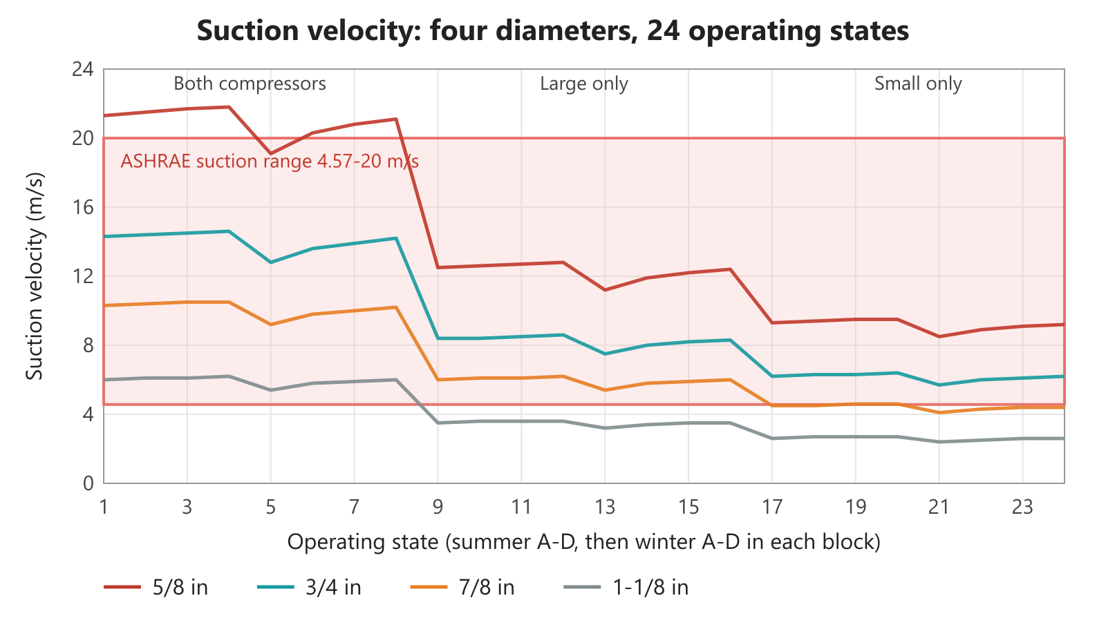
In this article we calculated four copper line diameters across 24 operating states of a rooftop unit designed to run in both summer and winter. The result shows that the diameter is set not by full load but by the smallest stage.
The unit handles 6,000 m³/h, uses R410A and has a single circuit. The circuit holds two scroll compressors of different sizes: Copeland ZP31K5E (small) and ZP42K5E (large). Together they deliver about 20 kW of cooling. The calculations were made with HVACinOne [13].
Why it matters
In this unit, with both compressors running, the gas lines consumed 0.7% (3/4 in) to 1.9% (5/8 in) of the capacity at summer point A. These figures belong to this design; they change with pipe length, diameter and compressor pair.
The order of magnitude is still informative. Under Eurovent Certita's rooftop certification rules, measured capacity may be at most 5% below the declared value [7]. If the declared value comes from a calculation without line losses, the line loss uses roughly 15% to 40% of that 5% allowance.
But the real risk is not capacity, it is oil return. The gas line diameter affects both the capacity and the life of the compressor.
Two pipes, two seasons
The two connections between the compressor and the four-way valve work as the same line in every season. The two pipes between the valve and the coils change with the season: in cooling, the pipe on the indoor coil side is the suction line and the one on the outdoor coil side is the discharge line. In heating this is reversed.
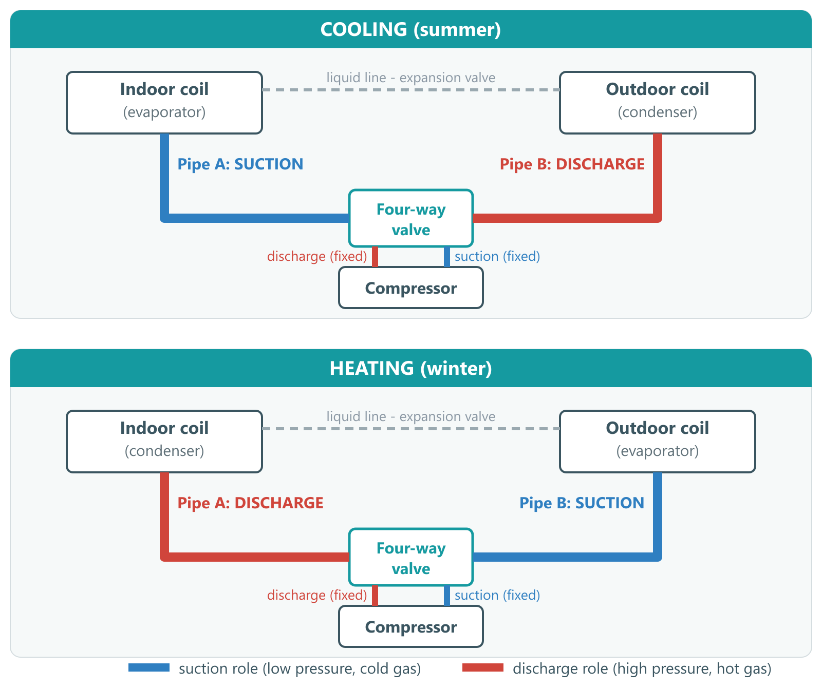
The pressure drop in the pipes changes the saturation temperature the compressor sees. We call this difference the saturation shift (K). In this study we calculated the shift with HVACinOne inside the cycle solution rather than as a correction added afterwards [13].
Every gas pipe must therefore be checked in two conditions: when it is the suction line and when it is the discharge line.
Sizing criteria: ASHRAE
We based the selection on the values recommended in the ASHRAE Handbook—Refrigeration [6]. ASHRAE gives these ranges considering economics, pressure drop, noise and oil return together [1].
| Line | Criterion | ASHRAE | Reason |
|---|---|---|---|
| Suction | Velocity | 4.57-20 m/s | Economics, pressure drop, noise, oil return |
| Suction | Saturation loss | ~1 K | Capacity loss, power increase |
| Discharge | Velocity | 10-18 m/s | Economics, pressure drop, noise, oil return |
Table 1 — ASHRAE criteria used in this study and their reasons.
What do other manufacturers say?
- Daikin: at least 2.54 m/s in horizontal suction and discharge lines, at least 5.08 m/s in risers. Suction and discharge loss 1.1-1.7 K. Written for field-piped systems [2].
- Danfoss: at least 4 m/s horizontally in the suction line, 8-12 m/s in risers, and an oil trap (U-bend) every 4 m in the riser [3].
- Copeland: at least 4 m/s horizontally and 8 m/s vertically in multiple-compressor units. It also notes that gas velocity drops when a single compressor runs [12].
- Lennox: suction velocity at most 10 m/s for noise. In risers, at least 6.1 m/s regardless of length (preferably 7.6 m/s), and an oil trap above 1.5 m of rise [10].
- York: suction loss at most 1.1 K, and an extra oil trap in vertical lines above 6 m. For risers it gives a minimum capacity table by diameter instead of a velocity [4].
- Copeland (system design): in the discharge line the oil is hot, so it flows at low velocities too. The minimum velocity matters mainly in risers at part load [11].
- Trane: in heating it requires the velocity in the hot gas riser to be enough to carry the oil. It also notes that the origin of these velocity rules is unclear [5].
Most of these rules are written for field-run lines. Daikin describes field-piped systems, Trane and Lennox describe split systems. The pipes inside a unit are short, and their vertical sections are around 0.5-2 m. We therefore departed from the sources on three points:
- No oil trap was needed. The trap thresholds in the sources range from 1.5 to 6 m. We accepted that a trap is not needed in the short vertical sections inside the unit. No source in this research explicitly exempts short rises inside a compact unit.
- We checked the vertical section by capacity instead of velocity. The 3/4 in pipe does not meet the manufacturers' fixed riser velocities (6.1-8 m/s) when the small compressor runs alone. We therefore used York's capacity-based table: for 3/4 in, the minimum capacity required is 2.1 kW in a suction riser and 3.2 kW in a hot gas riser [4]. With the small compressor alone at −7 °C, the evaporator capacity is about 4.7 kW, so both conditions are met. Because York's tables are given for different conditions, this is a preliminary check.
- We did not apply the noise limit inside the unit. The 3/4 in pipe exceeds Lennox's 10 m/s suction limit when both compressors run (12.8-14.6 m/s) [10]. That limit is written for split lines running through a building. For the short pipes inside a unit we used ASHRAE's 20 m/s upper limit.
Why the suction line decides the choice
A pipe that changes role with the season is the suction line for part of the year and the discharge line for the rest. Discharge gas is about 1.8-3 times denser than suction gas. In the same pipe and at the same mass flow, the discharge velocity is therefore that much lower.
In addition, the mass flow with both compressors running is about 4.7 times that of the smallest compressor alone. ASHRAE's discharge range (10-18 m/s) spans only a factor of 1.8 [6]. A diameter that stays within the ASHRAE suction range therefore never reaches 10 m/s on discharge. A diameter small enough to reach 10 m/s on discharge exceeds 20 m/s on suction.
So no single diameter satisfies both ranges, and one of the two lines must take priority. Priority belongs to the suction line, because:
- Oil is hard to carry in suction. The suction gas is cold and the oil thickens. The only thing carrying the oil back to the compressor is the gas velocity. In the discharge line the gas is hot and the oil thins, so it flows at low velocities too. The oil reaches the condenser and returns with the liquid; no velocity is needed for this in the liquid line [11]. ASHRAE likewise states that oil is carried at normal velocities when horizontal lines are level or pitched in the direction of flow [6].
- The same loss costs more in suction. According to Chemours' R410A table, a 1.1 K line loss reduces capacity to 96.4% in suction but only to 98.8% in discharge [1]. The loss in suction costs about three times as much capacity.
Lennox recommends the same order for heat pumps: a suction line correctly sized for oil transport and pressure drop also works properly as a discharge line in heating [10]. No source found in this research states the opposite. The only exception on the discharge side is the riser, where the gas must carry the oil against gravity; those sections are checked separately.
In our reading, the difference between ASHRAE's 10 m/s recommendation and Daikin's 2.54 m/s minimum also comes from this: ASHRAE recommends an economic design range, while Daikin gives the lowest value that still returns oil [2], [6].
We therefore sized the season-swapping pipes with ASHRAE's suction range, and accepted that the velocity stays below 10 m/s in the season when they are the discharge line.
Velocities by compressor state
The two gas pipes were taken at the same diameter and 3 m in length. Because the aim was only to compare pipe diameters, the fittings were kept identical in all calculations and the pressure drop of the four-way valve was left out.
Each diameter was solved in three compressor states and at the 4 points and 2 modes of EN 14825 [8]. Under the Ecodesign regulation, in the average climate the heating load is 88% of the design load at −7 °C and 15% at +12 °C [9]. The small compressor therefore normally runs alone at light load. However, it may also run alone at −7 °C after a defrost, during staged start-up, or in an oversized unit. For this reason we examined every state at every point.
In the tables below, values outside the ASHRAE suction range (4.57-20 m/s) are shown in bold.
| Point | 5/8 in | 3/4 in | 7/8 in | 1-1/8 in |
|---|---|---|---|---|
| Summer A (35 °C) | 21.3 | 14.3 | 10.3 | 6.0 |
| Summer B (30 °C) | 21.5 | 14.4 | 10.4 | 6.1 |
| Summer C (25 °C) | 21.7 | 14.5 | 10.5 | 6.1 |
| Summer D (20 °C) | 21.8 | 14.6 | 10.5 | 6.2 |
| Winter A (−7 °C) | 19.1 | 12.8 | 9.2 | 5.4 |
| Winter B (2 °C) | 20.3 | 13.6 | 9.8 | 5.8 |
| Winter C (7 °C) | 20.8 | 13.9 | 10.0 | 5.9 |
| Winter D (12 °C) | 21.1 | 14.2 | 10.2 | 6.0 |
Table 2a — Suction velocities with both compressors running (m/s).
| Point | 5/8 in | 3/4 in | 7/8 in | 1-1/8 in |
|---|---|---|---|---|
| Summer A (35 °C) | 8.9 | 6.0 | 4.4 | 2.6 |
| Summer B (30 °C) | 9.8 | 6.6 | 4.8 | 2.8 |
| Summer C (25 °C) | 10.9 | 7.4 | 5.3 | 3.1 |
| Summer D (20 °C) | 12.2 | 8.2 | 5.9 | 3.5 |
| Winter A (−7 °C) | 6.1 | 4.1 | 3.0 | 1.7 |
| Winter B (2 °C) | 7.3 | 4.9 | 3.6 | 2.1 |
| Winter C (7 °C) | 8.0 | 5.4 | 3.9 | 2.3 |
| Winter D (12 °C) | 8.7 | 5.9 | 4.2 | 2.5 |
Table 2b — Discharge velocities with both compressors running (m/s). Only 5/8 in reaches ASHRAE's 10 m/s recommendation, at summer points C and D.
At the highest mass flow, the suction velocity in the 5/8 in pipe exceeds 20 m/s at seven points, and the saturation shift approaches the 1 K limit at 0.81-0.85 K in summer. The other diameters stay within the ASHRAE suction range. At summer point A the shift and capacity loss are 0.30 K and 0.7% for 3/4 in, and 0.13 K and 0.3% for 7/8 in.
| Point | 5/8 in | 3/4 in | 7/8 in | 1-1/8 in |
|---|---|---|---|---|
| Summer A (35 °C) | 12.5 | 8.4 | 6.0 | 3.5 |
| Summer B (30 °C) | 12.6 | 8.4 | 6.1 | 3.6 |
| Summer C (25 °C) | 12.7 | 8.5 | 6.1 | 3.6 |
| Summer D (20 °C) | 12.8 | 8.6 | 6.2 | 3.6 |
| Winter A (−7 °C) | 11.2 | 7.5 | 5.4 | 3.2 |
| Winter B (2 °C) | 11.9 | 8.0 | 5.8 | 3.4 |
| Winter C (7 °C) | 12.2 | 8.2 | 5.9 | 3.5 |
| Winter D (12 °C) | 12.4 | 8.3 | 6.0 | 3.5 |
Table 3a — Suction velocities with the large compressor alone (ZP42K5E), in m/s.
| Point | 5/8 in | 3/4 in | 7/8 in | 1-1/8 in |
|---|---|---|---|---|
| Summer A (35 °C) | 6.2 | 4.2 | 3.0 | 1.8 |
| Summer B (30 °C) | 6.9 | 4.6 | 3.3 | 2.0 |
| Summer C (25 °C) | 7.7 | 5.2 | 3.7 | 2.2 |
| Summer D (20 °C) | 8.6 | 5.8 | 4.2 | 2.5 |
| Winter A (−7 °C) | 4.0 | 2.6 | 1.9 | 1.1 |
| Winter B (2 °C) | 5.0 | 3.3 | 2.4 | 1.4 |
| Winter C (7 °C) | 5.6 | 3.7 | 2.7 | 1.6 |
| Winter D (12 °C) | 6.2 | 4.2 | 3.0 | 1.8 |
Table 3b — Discharge velocities with the large compressor alone (m/s). No diameter reaches 10 m/s.
With the large compressor alone, 5/8 in, 3/4 in and 7/8 in stay within the ASHRAE suction range. 1-1/8 in is below the range at every point.
| Point | 5/8 in | 3/4 in | 7/8 in | 1-1/8 in |
|---|---|---|---|---|
| Summer A (35 °C) | 9.3 | 6.2 | 4.5 | 2.6 |
| Summer B (30 °C) | 9.4 | 6.3 | 4.5 | 2.7 |
| Summer C (25 °C) | 9.5 | 6.3 | 4.56 | 2.7 |
| Summer D (20 °C) | 9.5 | 6.4 | 4.6 | 2.7 |
| Winter A (−7 °C) | 8.5 | 5.7 | 4.1 | 2.4 |
| Winter B (2 °C) | 8.9 | 6.0 | 4.3 | 2.5 |
| Winter C (7 °C) | 9.1 | 6.1 | 4.4 | 2.6 |
| Winter D (12 °C) | 9.2 | 6.2 | 4.4 | 2.6 |
Table 4a — Suction velocities with the small compressor alone (ZP31K5E), in m/s. 7/8 in is below the lower limit at seven of the eight points and is marginal at 4.56 m/s at summer point C.
| Point | 5/8 in | 3/4 in | 7/8 in | 1-1/8 in |
|---|---|---|---|---|
| Summer A (35 °C) | 5.0 | 3.4 | 2.4 | 1.4 |
| Summer B (30 °C) | 5.6 | 3.8 | 2.7 | 1.6 |
| Summer C (25 °C) | 6.3 | 4.2 | 3.0 | 1.8 |
| Summer D (20 °C) | 7.1 | 4.8 | 3.4 | 2.0 |
| Winter A (−7 °C) | 3.1 | 2.1 | 1.5 | 0.9 |
| Winter B (2 °C) | 3.9 | 2.6 | 1.9 | 1.1 |
| Winter C (7 °C) | 4.4 | 3.0 | 2.1 | 1.3 |
| Winter D (12 °C) | 5.0 | 3.4 | 2.4 | 1.4 |
Table 4b — Discharge velocities with the small compressor alone (m/s). No diameter reaches 10 m/s.
With the small compressor alone the mass flow is lowest. 5/8 in and 3/4 in stay within the ASHRAE suction range, while 7/8 in and 1-1/8 in drop below it. As the mass flow falls, the suction problem moves from the small diameters to the large ones.
What the tables show
There are 24 states for each diameter. The number of states outside the ASHRAE suction range is 7 for 5/8 in, 0 for 3/4 in, 7 for 7/8 in and 16 for 1-1/8 in. 3/4 in is the only diameter that meets the ASHRAE suction range in all 24 states.
On the discharge side, no diameter reaches ASHRAE's 10 m/s recommendation in all states. 3/4 in falls below Daikin's 2.54 m/s value for horizontal sections only when the small compressor runs alone at −7 °C (2.1 m/s) [2].
With both pipes at 7/8 in, we reduced them to 5/8 in one at a time. When the pipe that is the suction line in summer is reduced, the summer capacity falls by 1.3-1.6% and winter is unchanged. When the pipe that is the suction line in winter is reduced, the winter capacity falls by 0.9-1.1% at points B-D and summer falls by at most 0.3%. The effect of pipe length is also small on 7/8 in pipes: going from 1.5 m to 6 m reduces the summer capacity by 0.07-0.15 kW.
By ASHRAE, the selection is 3/4 in. In horizontal sections the only point of attention is the small compressor running alone at −7 °C, so limiting this state through the control strategy is recommended. Risers are checked separately with the capacity table.
Result: a diameter for each gas line
Every pipe that works as a suction line should be 3/4 in: the two season-swapping pipes and the valve-to-compressor line, which is a suction line in every season. The line from the compressor to the valve is a discharge line in every season and can stay at 5/8 in.
This line reaches ASHRAE's 10 m/s recommendation only with both compressors running, at summer points C and D. A smaller diameter was not calculated in this study. A 3 m length of 5/8 in pipe adds 0.14-0.24 K of discharge saturation shift in summer compared with 7/8 in; this is an upper estimate for a short line. Danfoss requires at least 1 m of length in this line for its own compressors [3].
| Line | Summer / Winter | Recommended diameter | Velocity as suction line | Velocity as discharge line |
|---|---|---|---|---|
| Compressor to four-way valve | Discharge / Discharge | 5/8 in | — | 3.1-12.2 m/s |
| Four-way valve to compressor | Suction / Suction | 3/4 in | 5.7-14.6 m/s | — |
| Valve to indoor coil | Suction / Discharge | 3/4 in | 6.2-14.6 m/s (summer) | 2.1-5.9 m/s (winter) |
| Valve to outdoor coil | Discharge / Suction | 3/4 in | 5.7-14.2 m/s (winter) | 3.4-8.2 m/s (summer) |
Table 5 — Which line each gas pipe is in summer and winter, the recommended diameter and the velocity range across the three compressor states.
The lines between the compressor and the valve were not modelled separately; their velocities were taken from the calculation of pipes of the same diameter. The shift and capacity loss values above therefore do not include these two lines. If the valve-to-compressor line is also 3/4 in and of similar length, the suction shift of the complete system may increase by the share of that line, that is up to double. Even then, the summer A shift on 3/4 in stays below 1 K.
The model did not define which pipe carries the 0.5 m vertical section, so we ran the riser check with the lowest velocity for both pipes. Tandem assembly rules, the manufacturer's approval of this compressor pair, the suction accumulator recommended for reversible applications and the selection of the four-way valve are outside the scope of this article [3], [12].
Velocity ranges in heat pump design
The piping of a heat pump can be started from either the summer or the winter mode. But the velocity limits do not come from a single season. The upper limit must be checked at the highest mass flow and the lower limit at the lowest suction temperature with the smallest stage.
In this unit those were summer full load (14-15 m/s) and the small compressor at −7 °C in winter (5.7 m/s). In other words, the suction velocity at full load must be selected high enough to protect the lower limit. If the unit also runs below −7 °C, the lower limit must be checked at that temperature.
| Line | Criterion and target | Upper limit check | Lower limit check | In this unit |
|---|---|---|---|---|
| Valve to coils, as suction | Suction velocity 4.57-20 m/s | Highest mass flow | Lowest suction temperature, smallest stage | 5.7-14.6 m/s (3/4 in) |
| Valve to coils, as discharge | Check only, below 10 m/s accepted | — | Horizontal ≥2.54 m/s, riser: capacity table | 2.1-8.2 m/s |
| Valve to compressor | Suction velocity 4.57-20 m/s | Highest mass flow | Lowest suction temperature, smallest stage | 5.7-14.6 m/s (3/4 in) |
| Compressor to valve | Discharge velocity 10-18 m/s | Summer, all compressors | Below range accepted at part load | 3.1-12.2 m/s (5/8 in) |
| Suction line total | Saturation loss ~1 K | Summer, all compressors | — | 0.30 K (3 m pipe, 3/4 in) |
Table 6 — Selection criterion and target range for each gas line; the check states and results belong to this unit.
On pipes that work as discharge lines, staying below 10 m/s is accepted, but horizontal sections are checked against Daikin's 2.54 m/s and risers against York's capacity table [2], [4]. In this unit the velocity fell below 2.54 m/s in only one state. The ranges are based on ASHRAE, while the check states came out of this unit's results; they must be verified by calculation on another unit.
Practical takeaways
- Every gas line must be checked against the ASHRAE ranges in every compressor state and at every outdoor point. In this unit the upper suction limit was driven by all compressors in summer and the lower limit by the smallest compressor at −7 °C in winter.
- Season-swapping pipes are selected by the suction range. In risers carrying hot gas, oil return must be checked separately with the smallest compressor running.
- Long periods with only the smallest compressor running at low outdoor temperatures should be limited through the control strategy.
One-sentence lesson: In this roughly 20 kW asymmetric two-compressor heat pump, the diameter is set not by full load but by the smallest stage; of the four diameters tested, 3/4 in was the only one meeting ASHRAE's suction velocity range in every compressor state.
References
- Chemours, Opteon Refrigerant Piping Handbook, n.d., https://www.opteon.com/en/-/media/files/opteon/o-rph-opteon-refrigerant-piping-handbook.pdf
- Daikin Applied, AG 31-011 – Refrigerant Piping Design Guide, n.d., https://midwestengineering.ca/pub/resources/Mechanical%20Engineering/Daikin/daikin-refrigerant-piping-design-guide-daikin-ag-31-011-lr.pdf
- Danfoss, SH090–SH380 R410A Scroll Compressors – Application Guidelines (AB243586442172en), n.d., https://assets.danfoss.com/documents/latest/468662/AB243586442172en-001702.pdf
- Johnson Controls (York), DX Piping Guide 050.40-ES2, n.d., https://docs.johnsoncontrols.com/chillers/api/khub/documents/NPajozD7K49YECMkUwD3MA/content
- Trane, SS-APG010C-EN – Refrigerant Piping Application Guide (R-410A), 2020, https://www.trane.com/content/dam/Trane/Commercial/global/products-systems/equipment/air-handling/blower-coil-air-handlers/SS-APG010C-EN_05052020.pdf
- ASHRAE, ASHRAE Handbook – Refrigeration, Chapter 1 "Halocarbon Refrigeration Systems", 2022, https://handbook.ashrae.org/Handbooks/R22/SI/R22_Ch01/R22_ch01_si.aspx
- Eurovent Certita Certification, Technical Certification Rules ECP-13-Rooftop, Rev. 7, 2025, https://www.eurovent-certification.com/media/images/TCR/_EC/TCR_ECP-13_RT_2026_6930f011718a1.pdf
- CEN, EN 14825 – Testing and rating at part load conditions and calculation of seasonal performance, 2022, https://standards.iteh.ai/catalog/standards/cen/9fcc3835-2b65-478e-920e-3f3bacb6d2c5/en-14825-2022
- European Commission, Commission Regulation (EU) 2016/2281 – Ecodesign requirements for air heating products, cooling products, high temperature process chillers and fan coil units, 2016, https://eur-lex.europa.eu/eli/reg/2016/2281/oj
- Lennox, Refrigerant Piping Design and Fabrication Guidelines, Corp. 9351-L9, 2018, https://tech.lennoxintl.com/c03e7o14l/viu12ch2uv/corp9351l.pdf
- Copeland (Emerson), Refrigeration Manual Part 4 – System Design (AE104), n.d., https://media.copeland.com/2c65d92c-bb4b-48e1-96e4-b1aa011847e5/AE104-System%20Design.pdf
- Copeland, Technical Information TI_Scroll_ZR_ZP_Multiple – Multiple-compressor assemblies in air-conditioning applications, n.d., https://media.copeland.com/12398edc-63bf-46f5-b10f-b16b0106d401/C071702_0408_0718_E_TI_AC_Tandem_Trio.pdf
- HVACinOne, HVAC selection and calculation software – technical unit outputs (6,000 m³/h reversible rooftop, asymmetric compressor pair), 2026