A refrigeration cycle calculation often treats the circuit as if the pipes, valves and distributor were not there. On the real unit, every line has a pressure drop, so the compressor sees other temperatures than the coils. Every component also holds refrigerant. Do your calculations match the unit?
HVACinOne solves the refrigeration cycle with the parts it is built from. Straight pipe, fittings and valves, static head on vertical runs, the 4-way valve in both passes, velocity on every line, the expansion valve opening, the distributor pressure drop with nozzle and tube loading, and the charge against the compressor limit all go into the balance point. Summer and winter are solved with the line roles swapped. Every one of these moves the balance point, so every one is solved with it.
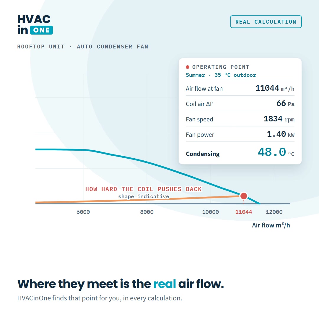
Take a rooftop circuit in cooling. Condensing at the coil is 48.2 °C, but the compressor discharges at 49.6 °C saturated: 1.39 K the compressor pays for. On the suction side the evaporator leaves at 6.4 °C and the compressor receives 4.4 °C, so 1.95 K is lost on the way back. The distributor takes 2.65 bar, and the expansion valve is 62 % open at the converged point. Charge, counted part by part, is 6.24 kg against a 5.90 kg compressor limit. Against the ideal circuit, capacity drops from 24.12 kW to 22.91 kW (−5.0 %), power input rises from 6.23 kW to 6.33 kW, EER falls from 3.87 to 3.62 (−6.5 %) and the charge grows from 5.45 kg to 6.24 kg (+14.5 %).
The size of each effect depends on the unit and its piping. The figures above are for this example only. This helps selection and product engineers see these effects at the desk, not on site.